Digital phase locked loop pdf
Digital Phase-Locked Loop and its Realization Tsai-Sheng Kao1, Sheng-Chih Chen2, Yuan-Chang Chang1, Sheng-Yun Hou1, and Chang-Jung Juan1 1Department of Electronic Engineering,
To the Graduate Council: I am submitting herewith a thesis written by Akila Gothandaraman entitled “Design and Implementation of an All Digital Phase Locked Loop using a Pulse Output Direct Digital Frequency Synthesizer.”
IEEE TRANSACTIONS ON CIRCUITS AND SYSTEMS—I: REGULAR PAPERS, VOL. XX, NO. Y, SEPTEMBER 2009 1 An FPGA-Based Linear All-Digital Phase-Locked Loop
1All Digital Phase Locked Loop Design and ImplementationAnitha Babu, Bhavya Daya, Banu Nagasundaram, Nivetha Veluchamy University of Florida, Gainesville, FL, 32608, USAAbstract An all digital phase locked loop was implemented, in 0.25 micron CMOS technology, by understanding the analog phase locked loop concepts and the digital conversion
How to Cite. Baker, R. J. (2010) Digital Phase-Locked Loops, in CMOS: Circuit Design, Layout, and Simulation, Third Edition, John Wiley & Sons, Inc., Hoboken, NJ, USA
A phase-locked loop is a feedback system combining a voltage controlled oscillator (VCO) and a phase comparator so connected that the oscillator maintains a constant phase …
Digital controlled oscillator – The variable ÷N counter is a down counter. Its content Its content starts with the number N loaded in parallel from the loop filter.
FPGA-BASED DIGITAL PHASE-LOCKED LOOP ANALYSIS AND IMPLEMENTATION BY DAN HU THESIS Submitted in partial fulfillment of the requirements for the degree of Master of Science in Electrical and Computer Engineering
a full digital phase locked loop Download a full digital phase locked loop or read online here in PDF or EPUB. Please click button to get a full digital phase locked loop book now.
Digital Phase Lock Loops Architectures and Applications by SALEH R. AL-ARAJI ZAHIR M. HUSSAIN RMIT University, Melbourne, Australia and MAHMOUD A. AL-QUTAYRI
PLL is a feedback loop where a voltage controlled oscil-lator can be automatically synchronize to a periodic input signal [22-24]. The basic PLL has three components
When the phase detector output voltage is applied through the loop filter to the VCO, ∆ω out – max = ± K V π/2 = ω L (lock range) where K V = K O K D , the product of the phase detector and VCO gains.
analysis of digital phase locked loops Download analysis of digital phase locked loops or read online here in PDF or EPUB. Please click button to get analysis of digital phase locked loops …
On Real Time Digital Phase Locked Loop Implementation with Application to Timing Recovery Roger Kippenberger, B.E.(hons) A thesis submitted in partial fulfillment
A Digital Phase-Locked Loop with Calibrated Coarse and Stochastic Fine TDC Amer Samarah, Anthony Chan Carusone Edward S. Rogers Sr. Department of Electrical and Computer Engineering
Loop filter: This filter is used to filter the output from the phase comparator in the phase locked loop, PLL. It is used to remove any components of the signals of which the phase is being compared from the VCO line, i.e. the reference and VCO input. It also governs many of the characteristics of the loop including the loop stability, speed of lock, etc.
The undersigned recommend to the Faculty of Graduate Studies and Research acceptance of this thesis “A Low Complexity Digital Phase-Locked Loop Based Frequency Synthesizer”
Phase locked loop frequency synthesizers Analog
https://youtube.com/watch?v=Mm7WfVzr1ao

DESIGN OF A PHASE LOCKED LOOP BASED CLOCKING CIRCUIT
Abstract—A novel fast locking digital phase-locked loop (DPLL) has been proposed with simple control unit charge pump (PCP); its outputto improve locking time. A frequency difference stage (FDS) is added to produce a 3-bit code represents the difference between the input frequency and the output frequency of the PLL. This code is used to control a programmable charge pump (PCP) output
The phase locked loop or PLL is a particularly flexible circuit building block. The phase locked loop, PLL can be used for a variety of radio frequency applications, from frequency synthesizers to clock recovery and FM demodulation.
Modern digital telecommunication and audio systems include a Digital Phase Locked Loop (D-PLL) in a form of a device or an algorithm. Wireless infrastructure, broadband wire-line networks and high
3/11/2016 · Phase locked loops are used in many radio frequency of RF systems. Phase locked loops are used in radios, as FM detectors as well as within …
Modeling and Simulating an All-Digital Phase Locked Loop By Russell Mohn, Epoch Microelectronics Inc. Send email toMike Woodward Implementing a PLL design on silicon can consume months of development time and hundreds of thousands of dollars in fabrication
Abstract — In this paper,a new digital phase- locked oop (DPLL) is proposedbased on finite impulse response (FIR) filters. The proposed DPLL is more robust to incorrect noise information
This article is available in PDF format for easy printing. Figure 1. How do you phase-lock the NCO to an external clock that is unrelated to the system clocks? Figure 2. PLL to phase-lock an NCO to an external clock (wide lines are complex signals). Hilbert Transformer. Here we’ll use the same 31-tap Hilbert transformer presented in an earlier post [2]. Its Matlab code is part of the m-file
Chapter 2 Digital Phase Lock Loops 2.1 Introduction The analog PLLs (APLLs) are still widely used, but digital PLLs (DPLLs) are attracting more attention for the significant advantages of digital systems
2 www.xilinx.com XAPP854 (v1.0) October 10, 2006 R Design The VCO performance dictates the performance of the PLL. Because the loop bandwidth of the
infinite impulse response (IIR) structure cannot solve this defect . Abstract — In this paper, a new digital phase-locked loop (DPLL) is proposed based on unbiased finite impulse response (UFIR) filters.
IEEE JOURNAL OF SOLID-STATE CIRCUITS, VOL. 38, NO. 2, FEBRUARY 2003 347 An All-Digital Phase-Locked Loop for High-Speed Clock Generation Ching-Che Chung and Chen-Yi Lee
Abstract The thesis “Modeling and Characterization of an All -Digital PLL” aims to create a behavioral model of an All -Digital Phase -Locked -Loop (ADPLL).
digital domain provides a certain edge towards them. The main motivation of the paper was the need of an accurate phase detection system which is easily realizable for an FPGA based linear all digital phase locked loop [1] which was required for a flexible offset local oscillator in a fast phase detection system for closed loop RF controls in the heavy ion particle accelerator SIS18 at GSI [2
2 Introduction 2.1 Phase Locked Loops (PLL) A phase locked loop is a device which generates a clock and sychronizes it with an input signal. The input signal can be data or another clock.

A Digital Phase-Locked Loop For Hard Disk Drive Read Channel Applications by John Leonard Wallberg Submitted to the Department of Electrical Engineering and Computer Science
IEEE Press, 1996. Design,”
second-order all-digital phase-locked loop (PLL) is proposed. The design procedure is based on the analogy between a type-II second-order analog PLL and an all-digital PLL.
https://youtube.com/watch?v=Q-h8zqRne-w
A Digital Phase-Locked Loop with Calibrated Coarse and
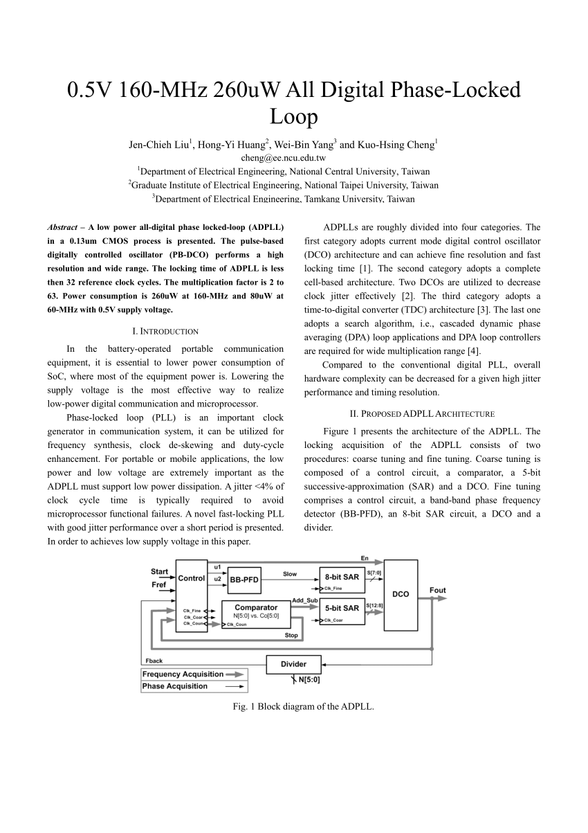
A low power all-digital phase locked-loop (ADPLL) in a 0.13um CMOS process is presented. The pulse-based digitally controlled oscillator (PB-DCO) performs a high resolution and wide range.
digital phase locked loop design and layout Wed, 21 Nov 2018 13:49:00 GMT digital phase locked loop design pdf – A phase-locked loop or phase lock loop (PLL) is
– increase in CP‟s phase noise due to finite BW of this feedback? •Minimal coupling to control voltage during switching and leakage when off – reduce jitter and phase drift
works with JK or EXOR phase detector. It has two counters .Both are independent .One is called Up and other is Down counter .But both counts in upward direction.
DIGITAL PHASE LOCK LOOPS Digital Phase Lock Loops Architectures and Applications by SALEH R. AL-ARAJI Etisalat University College, Sharjah, UAE ZAHIR M. HUSSAIN RMIT University, Melbourne, Australia
Digital Phase Locked Loop Design and Layout Dali Wang Fan Yang 12/21/2001
As its name implies, a phase-locked loop (PLL) is designed to lock the phase of an oscillator to the phase of a reference signal, providing a mechanism for synchronization on different platforms. In this example our input signal will be simply a complex sinusoid without noise or modulated information.
Chapter 1 Introduction and Overview 1.2 This Course and the Phase-Locked Loop Landscape 1.2.1 General PLL Perspective The focus of this course is phase-lock loops (PLLs) and syn-
Phase locked loops are incorporated into almost every large-scale mixed signal and digital system on chip (SOC). Various types of PLL architectures exist including fully analogue, fully digital, semi-digital, and software based. Currently the most commonly used PLL architecture for SOC environments and chipset applications is the Charge-Pump (CP) semi-digital type. This architecture is
Phase detector Wikipedia
DESIGN OF A PHASE LOCKED LOOP BASED CLOCKING CIRCUIT FOR HIGH SPEED SERIAL LINK APPLICATIONS BY RISHI RATAN THESIS Submitted in partial ful llment of the requirements
1 Data sheet acquired from Harris Semiconductor SCHS177A CD54/74HC297, CD74HCT297 High-Speed CMOS Logic Digital Phase-Locked-Loop Features • Digital Design Avoids Analog Compensation Errors
Digital Phase Locked Loop Induction Motor Speed Controller: Design and Experiments Mouna BEN HAMED and Lassaad SBITA 162 of the IM speed is synchronized with a reference signal, perfect signal speed regulation can be
One of the issues that faces the designers of very low phase noise synthesizers and phase locked loops, is a phenomenon referred to as the phase detector dead zone. This occurs where digital phase detectors are used. It is found that when the loop is in lock and there is a small phase difference between the two signals, very short pulses are created by the phase detector logic gates. Being
Digital Phase Lock Loops Home – Springer
A Fast Locking Digital Phase-Locked Loop using Frequency
cd74act297 digital phase-locked loop schs297d – august 1998 – revised june 2002 post office box 655303 • dallas, texas 75265 1 speed of bipolar fct, as, and s, with
· It consists of 2 digital phase detector, a charge pump and an amplifier. · Phase detector 1 is used in applications that require zero frequency and phase difference at lock. · Phase detector 2, if quadrature lock is desired, when detector 1 is used in the main loop, detector can
locked loop was implemented by understanding the analog phase locked loop concepts to obtain the same functionality. The pure digital phase locked loop is attractive because it is less sensitive to noise and operating conditions than its analog
ADI’s industry leading phase locked loop (PLL) synthesizer family features a wide variety of high performance, low jitter clock generation and distribution devices. The extensive, ever growing phase locked loop family now includes over 100 products, optimized for high data rate, low jitter clocking applications. The portfolio features PLLs
phase-locked-loop employing phase comparator I in locked condition of fo is shown in fig.2. Phase-comparator II is an edge-controlled digital memory network. It consists of four flip-flop stages, control gating, and a three-stage output-circuit comprising p- and n-type drivers having a common output node. When the p-MOS or n-MOS drivers are ON they pull the output up to VDD or down to VSS
ISSN: 2277-3754 ISO 9001:2008 Certified International Journal of Engineering and Innovative Technology (IJEIT) Volume 2, Issue 7, January 2013
Phase Locked Loops A PLL is a truly mixed-signal circuit, involving the co-design of RF, digital, and analog building blocks. A non-linear negative feedback loop that locks the phase of a
the phase jitter and the overall stability are tested for each individual configuration and different frequency relations. Keywords – Digital Phase Locked Loop, Digitally
Digital Phase Lock Loops Architectures and Applications

Phase Locked Loop Tutorial PLL Fundamtentals Radio
Phase locked loop frequency synthesizers Analog Integrated Circuit Design A video course under the NPTEL Nagendra Krishnapura Department of Electrical Engineering Indian Institute of Technology, Madras Chennai, 600036, India National Programme on Technology Enhanced Learning Nagendra Krishnapura Phase locked loop frequency synthesizers. Outline Phase locked loop(PLL) …
Digital phase lock loops are critical components of many communication, signal processing and control systems. This exciting new book covers various types of digital phase lock loops. It presents a comprehensive coverage of a new class of digital phase lock loops called the time delay tanlock loop
Chapter 5 Digital Phase-Locked Loop Abstract One of the most challenging tasks in analog circuit design is to adapt a functional block to ever-new CMOS process technologies.
3328 Junming Ye et al. / Procedia Engineering 29 (2012) 3327 – 3332 design DPLL. 2 All-Digital Phase-Locked Loop System Structure The all-digital phase-locked loop proposed by this paper mainly makes up of 6 parts, which are
SCHA002A CD4046B Phase-Locked Loop: A Versatile Building Block for Micropower Digital and Analog Applications 3 1 Introduction Phase-locked loops (PLLs), especially in monolithic form, have significantly increased use in
The phase detector is a key element of a phase locked loop and many other circuits. There are several types ranging from digital to analogue mixer and more. There are several types ranging from digital to analogue mixer and more.
A phase detector or phase comparator is a frequency mixer, analog multiplier or logic circuit that generates a voltage signal which represents the difference in phase between two signal inputs. It is an essential element of the phase-locked loop (PLL).
Phase-Locked Loops: A Control Centric Tutorial DanielAbramovitch Agilent Laboratories Communications and Optics Research Lab 3500 Deer Creek Road, M/S:25U-9
IJERTV5IS040128 Design of an Efficient Phase Frequency Detector for a Digital Phase Locked Loop Shaik. Yezazul Nishath School Of Electronics Engineering (SENSE)
Modeling and Simulating an All-Digital Phase Locked Loop
Resonant mechanical sensors are powerful tools for measuring, e.g., physical properties of fluids. Suitable systems for real-time monitoring of a sensor’s resonance behavior are, e.g., oscillator circuits and phase-locked-loop circuits.

https://youtube.com/watch?v=SS7z8WsXPMk
Phase Locked Loop Tutorial PLL Basics YouTube
LECTURE 080 – ALL DIGITAL PHASE LOCK LOOPS (ADPLL)
ALL Digital Phase-Locked Loop (ADPLL) A Survey IJFCC

Analysis Of Digital Phase Locked Loops Download eBook
https://youtube.com/watch?v=-t2bdjkoZzY
A Low Complexity Digital Phase-Locked Loop Based CURVE
DESIGN OF A PHASE LOCKED LOOP BASED CLOCKING CIRCUIT
FPGA-BASED DIGITAL PHASE-LOCKED LOOP ANALYSIS AND
Loop filter: This filter is used to filter the output from the phase comparator in the phase locked loop, PLL. It is used to remove any components of the signals of which the phase is being compared from the VCO line, i.e. the reference and VCO input. It also governs many of the characteristics of the loop including the loop stability, speed of lock, etc.
Chapter 2 Digital Phase Lock Loops 2.1 Introduction The analog PLLs (APLLs) are still widely used, but digital PLLs (DPLLs) are attracting more attention for the significant advantages of digital systems
Abstract—A novel fast locking digital phase-locked loop (DPLL) has been proposed with simple control unit charge pump (PCP); its outputto improve locking time. A frequency difference stage (FDS) is added to produce a 3-bit code represents the difference between the input frequency and the output frequency of the PLL. This code is used to control a programmable charge pump (PCP) output
3328 Junming Ye et al. / Procedia Engineering 29 (2012) 3327 – 3332 design DPLL. 2 All-Digital Phase-Locked Loop System Structure The all-digital phase-locked loop proposed by this paper mainly makes up of 6 parts, which are
Resonant mechanical sensors are powerful tools for measuring, e.g., physical properties of fluids. Suitable systems for real-time monitoring of a sensor’s resonance behavior are, e.g., oscillator circuits and phase-locked-loop circuits.
ISSN: 2277-3754 ISO 9001:2008 Certified International Journal of Engineering and Innovative Technology (IJEIT) Volume 2, Issue 7, January 2013
1All Digital Phase Locked Loop Design and ImplementationAnitha Babu, Bhavya Daya, Banu Nagasundaram, Nivetha Veluchamy University of Florida, Gainesville, FL, 32608, USAAbstract An all digital phase locked loop was implemented, in 0.25 micron CMOS technology, by understanding the analog phase locked loop concepts and the digital conversion
ADI’s industry leading phase locked loop (PLL) synthesizer family features a wide variety of high performance, low jitter clock generation and distribution devices. The extensive, ever growing phase locked loop family now includes over 100 products, optimized for high data rate, low jitter clocking applications. The portfolio features PLLs
Phase Locked Loops A PLL is a truly mixed-signal circuit, involving the co-design of RF, digital, and analog building blocks. A non-linear negative feedback loop that locks the phase of a
phase-locked-loop employing phase comparator I in locked condition of fo is shown in fig.2. Phase-comparator II is an edge-controlled digital memory network. It consists of four flip-flop stages, control gating, and a three-stage output-circuit comprising p- and n-type drivers having a common output node. When the p-MOS or n-MOS drivers are ON they pull the output up to VDD or down to VSS
All Digital Phase Locked Loop Design and Implementation
First Time Every Time – Practical Tips for Phase- Locked
infinite impulse response (IIR) structure cannot solve this defect . Abstract — In this paper, a new digital phase-locked loop (DPLL) is proposed based on unbiased finite impulse response (UFIR) filters.
Digital Phase Locked Loop Induction Motor Speed Controller: Design and Experiments Mouna BEN HAMED and Lassaad SBITA 162 of the IM speed is synchronized with a reference signal, perfect signal speed regulation can be
IJERTV5IS040128 Design of an Efficient Phase Frequency Detector for a Digital Phase Locked Loop Shaik. Yezazul Nishath School Of Electronics Engineering (SENSE)
The undersigned recommend to the Faculty of Graduate Studies and Research acceptance of this thesis “A Low Complexity Digital Phase-Locked Loop Based Frequency Synthesizer”
works with JK or EXOR phase detector. It has two counters .Both are independent .One is called Up and other is Down counter .But both counts in upward direction.
3/11/2016 · Phase locked loops are used in many radio frequency of RF systems. Phase locked loops are used in radios, as FM detectors as well as within …
Digital Phase Lock Loops Architectures and Applications by SALEH R. AL-ARAJI ZAHIR M. HUSSAIN RMIT University, Melbourne, Australia and MAHMOUD A. AL-QUTAYRI
IEEE Press, 1996. Design,”
Digital phase lock loops are critical components of many communication, signal processing and control systems. This exciting new book covers various types of digital phase lock loops. It presents a comprehensive coverage of a new class of digital phase lock loops called the time delay tanlock loop
the phase jitter and the overall stability are tested for each individual configuration and different frequency relations. Keywords – Digital Phase Locked Loop, Digitally
A Digital Phase-Locked Loop For Hard Disk Drive Read Channel Applications by John Leonard Wallberg Submitted to the Department of Electrical Engineering and Computer Science
locked loop was implemented by understanding the analog phase locked loop concepts to obtain the same functionality. The pure digital phase locked loop is attractive because it is less sensitive to noise and operating conditions than its analog
· It consists of 2 digital phase detector, a charge pump and an amplifier. · Phase detector 1 is used in applications that require zero frequency and phase difference at lock. · Phase detector 2, if quadrature lock is desired, when detector 1 is used in the main loop, detector can
Resonant mechanical sensors are powerful tools for measuring, e.g., physical properties of fluids. Suitable systems for real-time monitoring of a sensor’s resonance behavior are, e.g., oscillator circuits and phase-locked-loop circuits.
Chapter 1 Course Introduction/Overview
Digital Phase Lock Loops PDF Free Download
This article is available in PDF format for easy printing. Figure 1. How do you phase-lock the NCO to an external clock that is unrelated to the system clocks? Figure 2. PLL to phase-lock an NCO to an external clock (wide lines are complex signals). Hilbert Transformer. Here we’ll use the same 31-tap Hilbert transformer presented in an earlier post [2]. Its Matlab code is part of the m-file
Chapter 1 Introduction and Overview 1.2 This Course and the Phase-Locked Loop Landscape 1.2.1 General PLL Perspective The focus of this course is phase-lock loops (PLLs) and syn-
Phase Locked Loops A PLL is a truly mixed-signal circuit, involving the co-design of RF, digital, and analog building blocks. A non-linear negative feedback loop that locks the phase of a
A Digital Phase-Locked Loop with Calibrated Coarse and Stochastic Fine TDC Amer Samarah, Anthony Chan Carusone Edward S. Rogers Sr. Department of Electrical and Computer Engineering
FPGA-BASED DIGITAL PHASE-LOCKED LOOP ANALYSIS AND
Xilinx XAPP854 Digital Phase-Locked Loop (DPLL) Reference
Abstract The thesis “Modeling and Characterization of an All -Digital PLL” aims to create a behavioral model of an All -Digital Phase -Locked -Loop (ADPLL).
infinite impulse response (IIR) structure cannot solve this defect . Abstract — In this paper, a new digital phase-locked loop (DPLL) is proposed based on unbiased finite impulse response (UFIR) filters.
As its name implies, a phase-locked loop (PLL) is designed to lock the phase of an oscillator to the phase of a reference signal, providing a mechanism for synchronization on different platforms. In this example our input signal will be simply a complex sinusoid without noise or modulated information.
the phase jitter and the overall stability are tested for each individual configuration and different frequency relations. Keywords – Digital Phase Locked Loop, Digitally
Digital phase lock loops are critical components of many communication, signal processing and control systems. This exciting new book covers various types of digital phase lock loops. It presents a comprehensive coverage of a new class of digital phase lock loops called the time delay tanlock loop
On Real Time Digital Phase Locked Loop Implementation with Application to Timing Recovery Roger Kippenberger, B.E.(hons) A thesis submitted in partial fulfillment
works with JK or EXOR phase detector. It has two counters .Both are independent .One is called Up and other is Down counter .But both counts in upward direction.
Abstract—A novel fast locking digital phase-locked loop (DPLL) has been proposed with simple control unit charge pump (PCP); its outputto improve locking time. A frequency difference stage (FDS) is added to produce a 3-bit code represents the difference between the input frequency and the output frequency of the PLL. This code is used to control a programmable charge pump (PCP) output
This article is available in PDF format for easy printing. Figure 1. How do you phase-lock the NCO to an external clock that is unrelated to the system clocks? Figure 2. PLL to phase-lock an NCO to an external clock (wide lines are complex signals). Hilbert Transformer. Here we’ll use the same 31-tap Hilbert transformer presented in an earlier post [2]. Its Matlab code is part of the m-file
Digital controlled oscillator – The variable ÷N counter is a down counter. Its content Its content starts with the number N loaded in parallel from the loop filter.
– increase in CP‟s phase noise due to finite BW of this feedback? •Minimal coupling to control voltage during switching and leakage when off – reduce jitter and phase drift
How to Cite. Baker, R. J. (2010) Digital Phase-Locked Loops, in CMOS: Circuit Design, Layout, and Simulation, Third Edition, John Wiley & Sons, Inc., Hoboken, NJ, USA
3328 Junming Ye et al. / Procedia Engineering 29 (2012) 3327 – 3332 design DPLL. 2 All-Digital Phase-Locked Loop System Structure The all-digital phase-locked loop proposed by this paper mainly makes up of 6 parts, which are
IEEE Press, 1996. Design,”
Phase-Locked Loops A Control Centric Tutorial
Digital Phase Locked Loop Design and Layout MOSIS
Phase locked loops are incorporated into almost every large-scale mixed signal and digital system on chip (SOC). Various types of PLL architectures exist including fully analogue, fully digital, semi-digital, and software based. Currently the most commonly used PLL architecture for SOC environments and chipset applications is the Charge-Pump (CP) semi-digital type. This architecture is
2 Introduction 2.1 Phase Locked Loops (PLL) A phase locked loop is a device which generates a clock and sychronizes it with an input signal. The input signal can be data or another clock.
Chapter 2 Digital Phase Lock Loops 2.1 Introduction The analog PLLs (APLLs) are still widely used, but digital PLLs (DPLLs) are attracting more attention for the significant advantages of digital systems
1All Digital Phase Locked Loop Design and ImplementationAnitha Babu, Bhavya Daya, Banu Nagasundaram, Nivetha Veluchamy University of Florida, Gainesville, FL, 32608, USAAbstract An all digital phase locked loop was implemented, in 0.25 micron CMOS technology, by understanding the analog phase locked loop concepts and the digital conversion
3328 Junming Ye et al. / Procedia Engineering 29 (2012) 3327 – 3332 design DPLL. 2 All-Digital Phase-Locked Loop System Structure The all-digital phase-locked loop proposed by this paper mainly makes up of 6 parts, which are
To the Graduate Council: I am submitting herewith a thesis written by Akila Gothandaraman entitled “Design and Implementation of an All Digital Phase Locked Loop using a Pulse Output Direct Digital Frequency Synthesizer.”
On Real Time Digital Phase Locked Loop Implementation with Application to Timing Recovery Roger Kippenberger, B.E.(hons) A thesis submitted in partial fulfillment
digital domain provides a certain edge towards them. The main motivation of the paper was the need of an accurate phase detection system which is easily realizable for an FPGA based linear all digital phase locked loop [1] which was required for a flexible offset local oscillator in a fast phase detection system for closed loop RF controls in the heavy ion particle accelerator SIS18 at GSI [2
a full digital phase locked loop Download a full digital phase locked loop or read online here in PDF or EPUB. Please click button to get a full digital phase locked loop book now.
second-order all-digital phase-locked loop (PLL) is proposed. The design procedure is based on the analogy between a type-II second-order analog PLL and an all-digital PLL.
ISSN: 2277-3754 ISO 9001:2008 Certified International Journal of Engineering and Innovative Technology (IJEIT) Volume 2, Issue 7, January 2013
a full digital phase locked loop Download a full digital phase locked loop or read online here in PDF or EPUB. Please click button to get a full digital phase locked loop book now.
Digital Phase-Locked Loop and its Realization WSEAS
Chapter 5 Digital Phase-Locked Loop Home – Springer